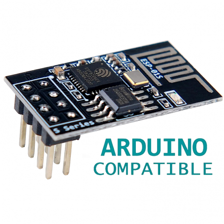


O módulo sem fios WIFI série ESP-01 ESP8266 é um SOC autónomo TCP/IP integrado que permite a qualquer microcontrolador aceder à sua rede WiFi. O ESP8266 pode alojar um programa de aplicação ou descarregar todas as funções de rede Wi-Fi de outra aplicação processadora.
DESCRIÇÃO EM PORTUGUÊS BREVEMENTE DISPONÍVEL
Se tiver alguma dúvida neste produto não hesite em contactar-nos.
*Atenção: as imagens são meramente ilustrativas.
The ESP8266EX chip, fitted to both ESP-01 and ESP-01S, is a simpler version of IOT ESP8266 chips but the most important point is that the chip lets you do standard IOT operations - in the same way that all ESP chips are capable of doing.
Here's a list of its features:
The Flash chip fitted to the board is an extra storage area providing either 32MBit (4 Mbyte), 8Mbit (1MByte). The following are some of the most common chip markings:
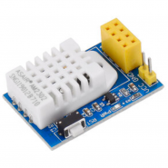
At first glance, the two modules look the same. However, a close examination of the boards will show the difference in the number of LEDs (Light Emitting Diodes). Please see Figure 2 below. In the original ESP-01, there are two (2) small LEDs. On the other hand, the ESP-01S has a single, bigger LED.
The difference becomes more apparent when you supply power to the boards. The ESP-01 board will have a red LED light turned on indicating the presence of power. On the ESP-01S board, you will only see a blue LED flash for a while when the power is applied.
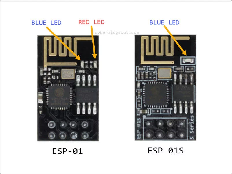
Figure 2. Physical Comparison of ESP-01 and ESP-01S Modules
Although both boards have a blue serial-activity LED, the blue LEDs are wired differently. See Figure 3. In the ESP-01 board, the blue LED is connected on the VCC and the TX pins, while on the ESP-01S, it is connected on the VCC and the GPIO2 pins. On both boards, a 2.2K ohms resistor is used in series with the blue LED as a current limiter.
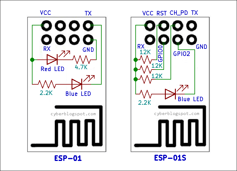
Figure 3. Internal Wiring Comparison of ESP-01 and ESP-01S Modules
Another difference between ESP-01 and ESP-01S is the presence of three (3) pull-up resistors on the ESP-01S module. Pull-up resistors are used to provide a logic HIGH signal to a circuit. As shown on the right side of Figure 3 above, three (3) 12K-ohm resistors are connected from the VCC to the RESET, GPIO0, and CH_PD pins on the ESP-01S board.
Prior to the availability of the ESP-01S module, a popular ESP-01 wiring scheme for adding a reset switch and a programming switch is shown below in Figure 4. First of all, in order to power up the ESP-01 board, you need to pull up the CH_PD (Chip Enable/Power Down) pin. Next, you connect the RESET pin to the VCC because you do not want the RESET pin hanging and be vulnerable to noise causing unexpected resets. And third, pulling up the GPIO0 pin to VCC will automatically run the program or sketch loaded on the ESP-01 module after a power up or a reset.
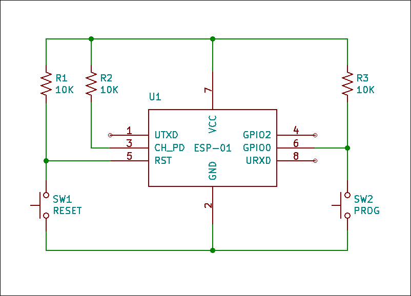
Figure 4. Schematic Diagram of ESP-01 with Reset and Programming Switches
On the newer ESP-01S module, the circuit shown above will be a lot more simple. There is no need to externally supply the three (3) pull-up resistors. See Figure 5.
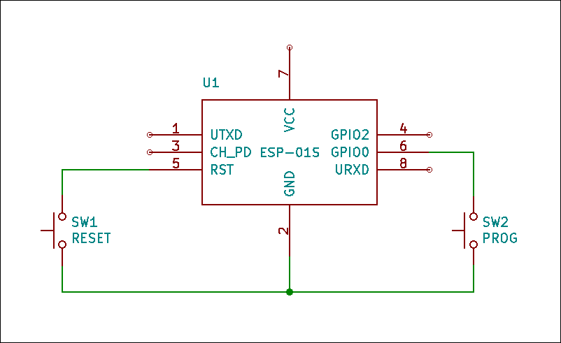
Figure 5. Schematic Diagram of ESP-01S with Reset and Programming Switches
The ESP-01 and the ESP-01S Wi-Fi modules are functionally the same. The ESP-01S module is a newer version of the original ESP-01 module. The ESP-01 module has a red power indicator LED that is absent on the ESP-01S. Both modules have a blue LED that indicates serial activity. However, the blue LED is wired differently on each module’s version. And finally, the ESP-01S module has three (3) on board pull-up resistors that are missing on an ESP-01 module.
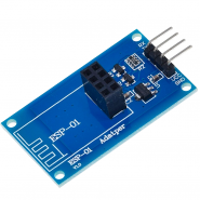
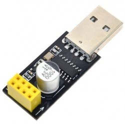
ESP-01 USB-to-Serial Converter Programmer Module
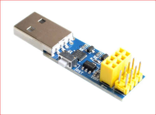
Figure 1. ESP-01 USB-to-serial Converter Programmer Module
The ESP-01 programmer module shown in Figure 1 uses the Silabs CP2104 USB-to-serial converter chip. Other ESP-01 programmer modules use the CH340 chip. With this kind of programmer module, you do not have to worry about switching the ESP-01 module from RUN mode to PROGRAMMING mode. ESP-01 modules have what we call boot modes (see Table 1 below). That is, when they are powered up or when they are reset, depending on the state of the GPIO0 pin, they either RUN the program on their flash memory or enter into PROGRAMMING mode. With the programmer module above, everything is automatic. The ESP-01 module automatically switches into PROGRAMMING mode when you hit the Upload button on the Arduino IDE.
DIY USB-to-serial Converter Programmer
If you do not have an ESP-01 USB-to-serial converter programmer module, you can make your own programmer if you have a USB-to-serial converter. Figure 2 shows some examples of USB-to-serial converters.
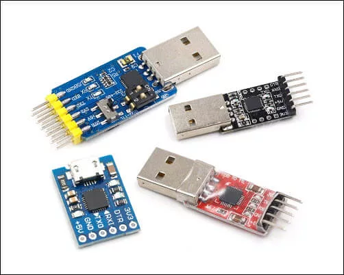
Figure 2. USB-to-Serial (TTL) Converters
Below is an schematic diagram of an ESP-01 programmer using a USB to TTL converter module. This is the preferred ESP-01 programmer while breadboarding because all the ESP-01 pins are accessible.
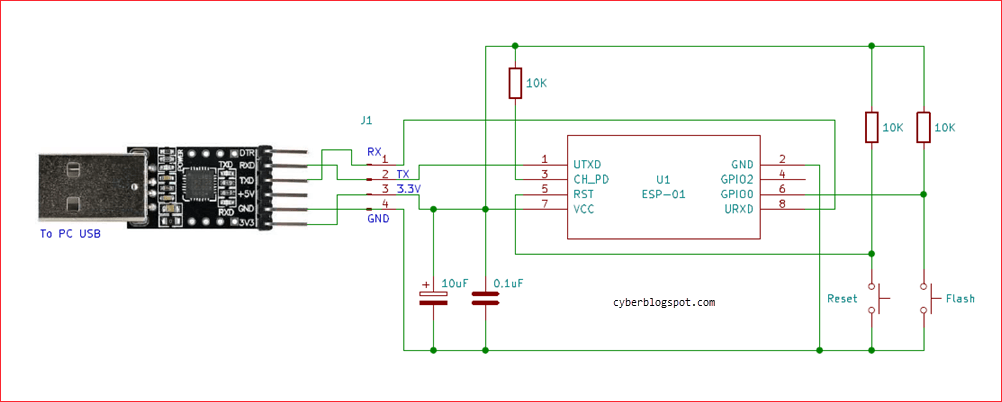
Figure 3. ESP-01 Programmer Using a USB-to-serial TTL Converter
About the Circuit
The three (3) 10k resistors are pull-up resistors necessary to ensure that the ESP8266 pins are on their proper logic levels. The two capacitors are optional components to increase the stability of the programmer. The 10 microfarad capacitor serves as an additional ac ripple filter while the 0.1 microFarad (100 nanoFarad) capacitor is used as high-frequency filter.
The RESET and PROGRAM switches are push-button switches. Pressing and then releasing the RESET switch will boot and run the program loaded in the flash memory. Pressing and releasing the RESET switch, while at the same time holding down the PROGRAM switch, will place the ESP-01 into the UART Bootloader mode, or go into programming mode. See the table below.
Again, the sequence of switch presses in order to go into programming mode is: press and hold down the PROGRAM switch, press and release the RESET switch, and finally release the PROGRAM switch.
Boot Mode Table
| GPIO-2 | GPIO-0 | Boot Mode |
| HIGH | LOW | UART Bootloader (Programming Mode) |
| HIGH | HIGH | Run program in flash |
Table 1. ESP-01 Module Boot Mode Table
Arduino Board as ESP-01 Programmer
Another option for an ESP-01 programmer is an Arduino board. You can use any Arduino board available – Arduino Uno, Arduino Nano, Arduino Mega, etc. Figure 4 is an schematic diagram of an Arduino Uno board used as an ESP-01 programmer. Note that it is exactly the same schematic diagram shown in Figure 3, only with the USB-to-serial converter being replaced by an Arduino Uno board. For more information about using an Arduino board as ESP-01 programmer, please see – ESP-01 and ESP-01S Pinout and Configuration.
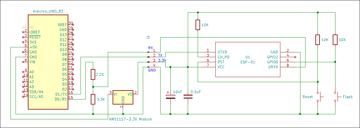
Figure 4. Arduino Uno as ESP-01 Programmer
To program the ESP-01 using the Arduino IDE, the ESP8266 core for Arduino must first be installed. Please see, How to Set up Arduino IDE for ESP8266 Programming.
If you don’t have the Arduino IDE installed yet, and you’re using Windows 10, see: How to Install Arduino IDE on Windows 10.
The first lesson for programming the ESP-01 with the Arduino IDE is the Blink sketch. Open the Arduino IDE, create a new sketch, then, copy and paste the Blink program below.
|
void setup() {
pinMode(LED_BUILTIN, OUTPUT); // Initialize the LED_BUILTIN pin as an output
}
// the loop function runs over and over again forever
void loop() {
digitalWrite(LED_BUILTIN, LOW); // Turn the LED on (Built-in LED on ESP-01 is active LOW)
delay(1000); // Wait for a second
digitalWrite(LED_BUILTIN, HIGH); // Turn the LED off by making the voltage HIGH
delay(2000); // Wait for two seconds (to demonstrate the active low LED)
}
|
Before uploading the sketch to the ESP-01 module, first, make sure that you have selected the right board which is “Generic ESP8266 Module”. Please refer to Figure 5.
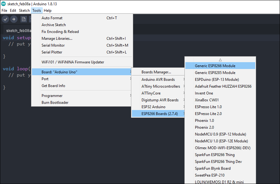
Figure 5. Arduino IDE Board Selection
Also, make sure that the appropriate serial COM port for your ESP-01 programmer is selected. If it is your first time to use your ESP-01 programmer, you may have to install the device driver for your ESP-01 programmer.
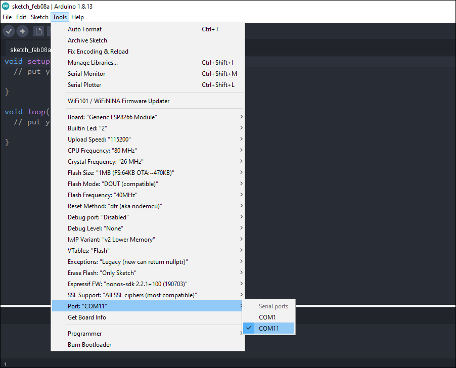
Figure 6. Arduino IDE Serial COM Port Selection
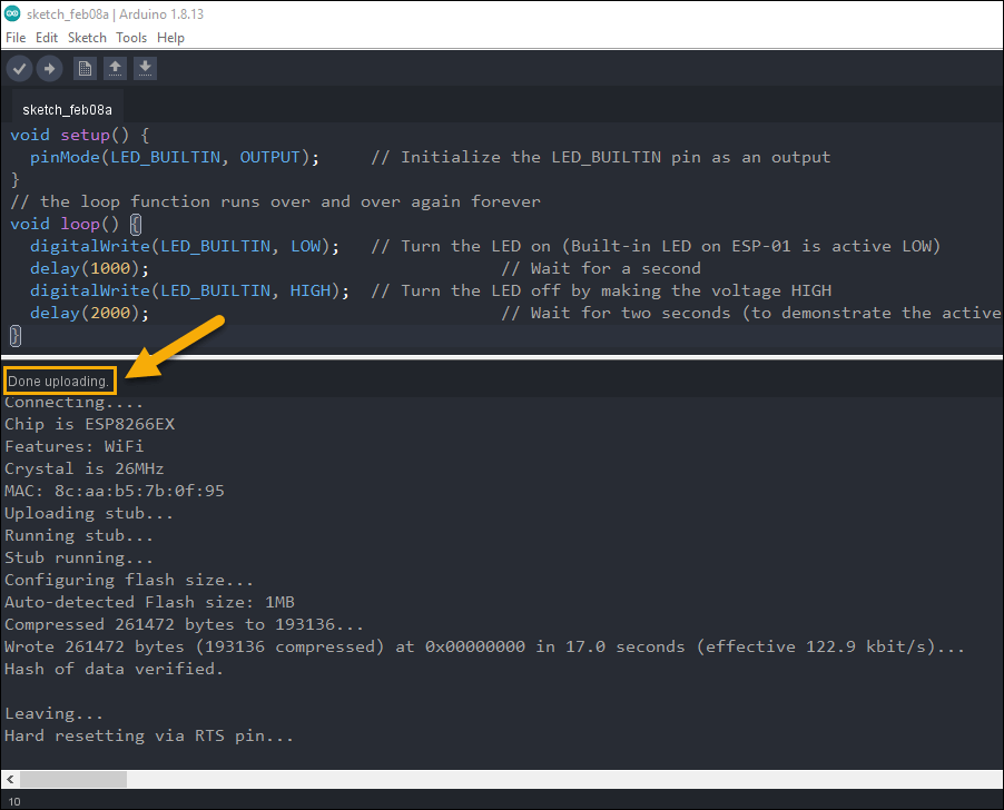
After selecting the right board and the correct serial COM port, click the Upload button. Following a successful upload with the message “Done uploading” (see Figure 7), the blue built-in LED on your ESP-01 board should start flashing.
If the LED does NOT flash, you must be using a different version of ESP-01 module. You may have to change the “Built-in LED:” setting on the Arduino IDE. If you want to know why, please see the article entitled Difference Between ESP-01 and ESP-01S.
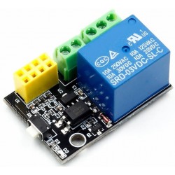
One of the popular uses of ESP-01 module is in IoT (Internet of Things) applications. The ESP-01 module can be used to control a switch (relay) remotely or wirelessly through Wi-Fi. This enables any device (light, motor, etc.) connected to the relay to be turned on and off remotely. To learn more on how to implement this, see the following articles.

Produtos Associados

O módulo sem fios WIFI série ESP-01 ESP8266 é um SOC autónomo TCP/IP integrado que permite a qualquer microcontrolador aceder à sua rede WiFi. O ESP8266 pode alojar um programa de aplicação ou descarregar todas as funções de rede Wi-Fi de outra aplicação processadora.