SRF05 - Ultrasons


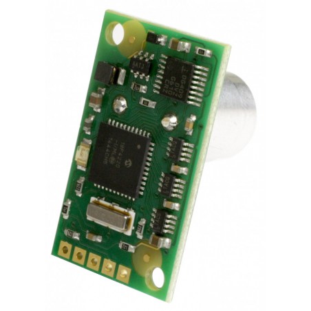
O SRF235 é um pequeno sonar com um transdutor acoplado semi-industrial, que proporciona uma largura de banda muito estreita de 15 ° e um ciclo rápido - taxa de atualização de 100Hz.
DESCRIÇÃO EM PORTUGUÊS BREVEMENTE DISPONÍVEL
Se tiver alguma dúvida neste produto não hesite em contactar-nos.
*Atenção: as imagens são meramente ilustrativas.
SRF235 Ultrasonic range finder
Technical Specification
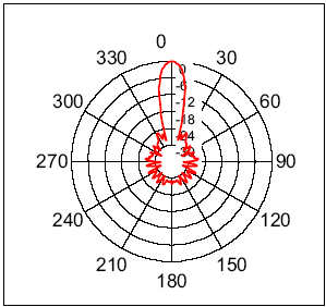
The SRF235 is a narrow beam ultrasonic ranger, with a beam width of just 15°. An industrial high frequency air coupled transducer operating at 235KHz is used for both Transmit and Receive. The beam patterns below show compare the 15° SRF235 with the 55° typical pattern of the SRF04.
 |
 |
|
SRF235 Beam Pattern |
SRF04 Beam pattern |
Limitations & Characteristics
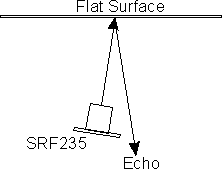
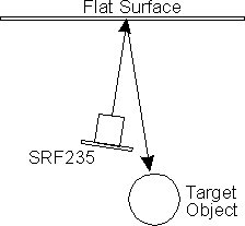
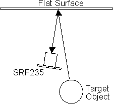
235KHz ultrasound does not transmit as easily through air as 40KHz does, so the range of the SRF235 is limited to around 1 meter for normal objects out to a maximum of 1.2 meters for a large surface. The use of a single transducer for both transmit and receive means there is a blanking zone out to 10cm, so the effective range is 10cm to 1.2m. The 235KHz narrow 15° beam behaves more like light on a mirror than 40KHz sensors, so looking at a hard flat surface at an angle of more than 8° or 9° will not yield an echo from that surface. It may be that the reflected beam hits an object and bounces back. In this case the echo from the object will detected and the sonar will indicate the total range of sonar to flat surface + flat surface to object. The flat surface its self will be invisible to the sonar. Under the same circumstances, a 40KHz sensor such as the SRF04 would detect the flat surface - not the reflected object.
 |
 |
 |
| At an angle of just 9 degrees, the beam does not reflect back to the sonar |
Here there is an object in the path of the reflected beam. The beam will bounce off the object and - |
back via the flat surface to the sonar, which will think there is an object off in the distance in front of it. |
Soft furnishings do not reflect well at 235KHz and might not be detected. Please be aware of these characteristics before considering the purchase of an SRF235.
The SRF235 detects hard round objects well, such as table and chair legs etc. This makes the SRF235 ideal for detailed local mapping around the robot, but not for longer range sensing. Using the SRF235 along side a 40KHz sonar, makes an excellent sensor combination.
Communication
Communication with the SRF235 ultrasonic rangefinder is via the I2C bus. This is available on popular controllers such as the OOPic, Stamp BS2p, PicAxe etc. as well as a wide variety of micro-controllers. To the programmer the SRF235 behaves in the same way as the ubiquitous 24xx series EEPROM's, except that the I2C address is different. The default shipped address of the SRF235 is 0xE0. It can be changed by the user to any of 16 addresses E0, E2, E4, E6, E8, EA, EC, EE, F0, F2, F4, F6, F8, FA, FC or FE, therefore up to 16 sonar's can be used.
Connections
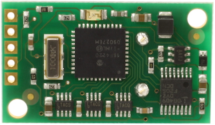
The connections to the SRF235 are identical to the SRF08and SRF10 rangers. The "No Connection" pin should be left unconnected. It is actually the CPU MCLR line and is used once only in our workshop to program the PIC18F4220 on-board after assembly, and has an internal pull-up resistor. The SCL and SDA lines should each have a pull-up resistor to +5v somewhere on the I2C bus. You only need one pair of resistors, not a pair for every module. They are normally located with the bus master rather than the slaves. The SRF235 is always a slave - never a bus master. If you need them, I recommend 1.8k resistors. Some modules such as the OOPic already have pull-up resistors and you do not need to add any more.
| +5v SDA SCL Do not connect GND |
 |
Registers
The SRF235 appears as a set of 4 registers.
|
Location |
Read |
Write |
|
0 |
Software Revision |
Command Register |
|
1 |
Unused (reads 0x80) |
N/A |
|
2 |
Range High Byte |
N/A |
|
3 |
Range Low Byte |
N/A |
Only location 0 can be written to. Location 0 is the command register and is used to start a ranging session. It cannot be read. Reading from location 0 returns the SRF235 software revision. The ranging lasts for 10mS, and the SRF235 will not respond to commands on the I2C bus whilst it is ranging.
Locations, 2 and 3, are the 16bit unsigned result from the latest ranging - high byte first. The meaning of this value depends on the command used, and is either the range in inches, or the range in cm or the flight time in uS. A value of 0 indicates that no objects were detected. A new ranging may be initiated as soon as you have the read the range from the last one - no delays are needed.
Commands
The are three commands to initiate a ranging (80 to 82), to return the result in inches, centimeters or microseconds. There is also a set of commands to change the I2C address.
| Command | Action | |
| Decimal | Hex | |
| 80 | 0x50 | Ranging Mode - Result in inches |
| 81 | 0x51 | Ranging Mode - Result in centimeters |
| 82 | 0x52 | Ranging Mode - Result in micro-seconds |
| 160 | 0xA0 | 1st in sequence to change I2C address |
| 165 | 0xA5 | 3rd in sequence to change I2C address |
| 170 | 0xAA | 2nd in sequence to change I2C address |
Ranging
To initiate a ranging, write one of the above commands to the command register and wait the required amount of time for completion and read the result. The echo buffer is cleared at the start of each ranging. The ranging lasts for 10mS, after this the range can be read from locations 2 and 3.
Checking for Completion of Ranging
You do not have to use a timer on your own controller to wait for ranging to finish. You can take advantage of the fact that the SRF235 will not respond to any I2C activity whilst ranging. Therefore, if you try to read from the SRF235 (we use the software revision number a location 0) then you will get 255 (0xFF) whilst ranging. This is because the I2C data line (SDA) is pulled high if nothing is driving it. As soon as the ranging is complete the SRF235 will again respond to the I2C bus, so just keep reading the register until its not 255 (0xFF) anymore. You can then read the sonar data. Your controller can take advantage of this to perform other tasks while the SRF235 is ranging.
LED
The red LED is used to flash out a code for the I2C address on power-up (see below). It also gives a brief flash during the "ping" whilst ranging.
Changing the I2C Bus Address
To change the I2C address of the SRF235 you must have only one sonar on the bus. Write the 3 sequence commands in the correct order followed by the address. Example; to change the address of a sonar currently at 0xE0 (the default shipped address) to 0xF2, write the following to address 0xE0; (0xA0, 0xAA, 0xA5, 0xF2 ). These commands must be sent in the correct sequence to change the I2C address, additionally, No other command may be issued in the middle of the sequence. The sequence must be sent to the command register at location 0, which means 4 separate write transactions on the I2C bus. When done, you should label the sonar with its address, however if you do forget, just power it up without sending any commands. The SRF235 will flash its address out on the LED. One long flash followed by a number of shorter flashes indicating its address. The flashing is terminated immediately on sending a command the SRF235.
| Address | Long Flash | Short flashes | |
| Decimal | Hex | ||
| 224 | E0 | 1 | 0 |
| 226 | E2 | 1 | 1 |
| 228 | E4 | 1 | 2 |
| 230 | E6 | 1 | 3 |
| 232 | E8 | 1 | 4 |
| 234 | EA | 1 | 5 |
| 236 | EC | 1 | 6 |
| 238 | EE | 1 | 7 |
| 240 | F0 | 1 | 8 |
| 242 | F2 | 1 | 9 |
| 244 | F4 | 1 | 10 |
| 246 | F6 | 1 | 11 |
| 248 | F8 | 1 | 12 |
| 250 | FA | 1 | 13 |
| 252 | FC | 1 | 14 |
| 254 | FE | 1 | 15 |
Take care not to set more than one sonar to the same address, there will be a bus collision and very unpredictable results.
Examples:
I2C bus tutor - general I2C guide
Arduino - using an I2C interface and LCD03/LCD05
ATMEGA32 - reading the result and displaying on a LCD03/LCD05
BS2 stamp - I2C communication, writes to the debug console
PIC18F4410 - reading the result and displaying on a LCD03/LCD05
PIC24FJ16GA002 - reading the result and displaying on a LCD03/LCD05
Picaxe18x - I2C communication exampe
PicBasic PRO - uses the PIC16F877
Raspberry Pi - using I2C communication
Produtos Associados

