

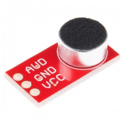
Adicione um ouvido ao seu projeto com o módulo amplificador de microfone MAX4466.
É um módulo bem concebido com tensão de alimentação flexível e ganho ajustável, sendo adequado para uma vasta gama de aplicações de áudio. Este módulo é particularmente adequado para projetos como trocadores de voz em tempo real, gravação/amostragem de áudio e projetos reativos de áudio que utilizam algoritmos Fast Fourier Transform (FFT).
DESCRIÇÃO EM PORTUGUÊS BREVEMENTE DISPONÍVEL
Se tiver alguma dúvida neste produto não hesite em contactar-nos.
*Atenção: as imagens são meramente ilustrativas.
Do you know how Microphones work?
Inside a microphone, there is a thin diaphragm and a backplate. Together, they form a capacitor.

When you speak into the microphone, the sound waves produced by your voice hit the diaphragm, making it vibrate.
As the diaphragm vibrates, it moves closer or farther away from the backplate. This movement changes the capacitance between them. This change in capacitance produces a voltage across the plates, which we can measure to determine the amplitude of the sound.
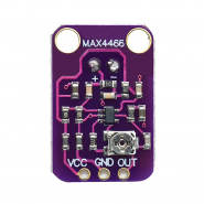
At the core of the module is a micropower op-amp, the Maxim MAX4466, specifically designed for use as a microphone amplifier. Due to its high common-mode rejection and outstanding power-supply rejection ratio, the MAX4466 is an excellent choice for noisy environments. As a result, this amplifier delivers exceptional sound quality, free from the noise or scratchiness often found in other microphone amplifier breakouts.

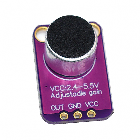
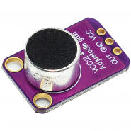
The module also includes an electret microphone capable of capturing sound waves ranging from 20 Hz to 20 kHz, as well as the necessary supporting circuitry to drive the MAX4466.

Moreover, the module includes SMD ferrite beads that are connected in series with the power supply rails. These beads play a crucial role in suppressing electromagnetic emissions; they block low-frequency noise and absorb high-frequency noise, further enhancing the common-mode rejection ratio.

On the back of the module, there is a small trimmer potentiometer used to adjust the gain. The gain determines how much the module amplifies the sound signal. Rotating the potentiometer counterclockwise (CCW) increases the gain, while turning it clockwise (CW) decreases the gain.

The gain can be adjusted anywhere from 25x to 125x. At its lowest setting, it amplifies to roughly 200 mVpp (suitable for normal speaking volume about 6 inches away)—ideal for connecting to devices that expect ‘line level’ input without clipping. On the higher end, it can amplify up to about 1Vpp, which is ideal for reading from a microcontroller’s ADC. It’s worth noting that the output is rail-to-rail, meaning that if the sounds get loud enough, the output can reach up to 5 Vpp!
Using the module is straightforward: connect the GND pin to ground and the VCC pin to 2.4-5VDC. The audio waveform will come out of the OUT pin, which can be directly connected to the microcontroller’s ADC pin. Please note that the output will have a DC bias equal to VCC/2, so when it’s perfectly quiet, the voltage will remain steady at a VCC/2 level.
The module has three pins.

VCC is the power supply pin that accepts 2.4V to 5.5V DC voltage.
GND is the ground pin.
OUT is the analog output pin that delivers the amplified sound signal. Please note that the output will have a DC bias equal to VCC/2, so when it’s perfectly quiet, the voltage will remain steady at a VCC/2 level.
The wiring is relatively simple. There are only three wires to connect: two for power and one for output.
The VCC of the MAX4466 module can range between 2.4-5VDC. For optimal performance, it’s recommended to use the 3.3V pin as it provides the “quietest” supply on the Arduino. Therefore, power the sensor with 3.3V and connect ground to ground. Then connect the output to an analog input pin. In this example we’ll use pin A0.
The following table lists the pin connections:
| MAX4466 Module | Arduino | |
| VCC | 3.3V | |
| GND | GND | |
| OUT | A0 |
The wiring is shown in the image below.

The output from the MAX4466 amplifier is simply a varying voltage. To measure the sound level, we need to take multiple measurements to find the minimum and maximum values, or, in technical terms, the ‘peak-to-peak amplitude,’ of the signal.
In the example code below, we chose a sample window of 50 milliseconds. This duration is sufficient to measure sound levels for frequencies as low as 20 Hz, which is the lowest frequency that humans can hear. After finding the minimum and maximum samples, we compute the difference (to get the peak-to-peak amplitude of the sound) and convert it to volts. The output is then printed to the serial monitor.
const int sampleWindow = 50;  // Sample window width in mS (50 mS = 20Hz)
int const AMP_PIN = A0;       // Preamp output pin connected to A0
unsigned int sample;

void setup()
{
  Serial.begin(9600);
}

void loop()
{
  unsigned long startMillis = millis(); // Start of sample window
  unsigned int peakToPeak = 0;   // peak-to-peak level

  unsigned int signalMax = 0;
  unsigned int signalMin = 1024;

  // collect data for 50 mS and then plot data
  while (millis() - startMillis < sampleWindow)
  {
    sample = analogRead(AMP_PIN);
    if (sample < 1024)  // toss out spurious readings
    {
      if (sample > signalMax)
      {
        signalMax = sample;  // save just the max levels
      }
      else if (sample < signalMin)
      {
        signalMin = sample;  // save just the min levels
      }
    }
  }
  peakToPeak = signalMax - signalMin;  // max - min = peak-peak amplitude
  Serial.println(peakToPeak);
  //double volts = (peakToPeak * 5.0) / 1024;  // convert to volts
  //Serial.println(volts);
}
Once you have uploaded the sketch, open the serial monitor and set the baud rate to 9600. Now, try snapping your fingers near the sensor; you will observe a change in the readings.

Serial data can be hard to visualize if you’re only looking at values. If you are using the Arduino IDE v1.6.6+, there is an option to view the data on a graph using the Arduino Serial Plotter.
In the Arduino IDE, choose Tools > Serial Plotter. You should observe a waveform similar to the image below, when you snap your fingers near the sensor.

The code begins by defining a few constants and variables.
First, a constant named sampleWindow is defined, which sets the sample window width in milliseconds. It’s set to 50, which corresponds to 20 Hz. Next, another constant AMP_PIN is defined, which represents the analog pin A0 where the output from the MAX4466 module is connected. An unsigned integer variable named sample is also defined to hold the values read from the AMP_PIN.
const int sampleWindow = 50;  // Sample window width in mS (50 mS = 20Hz)
int const AMP_PIN = A0;       // Preamp output pin connected to A0
unsigned int sample;
In setup(), the Serial Monitor is initialized for debugging purposes.
void setup() {
  Serial.begin(9600);
}
At the beginning of the loop() function, the current time (in milliseconds since the Arduino started) is stored in the variable startMillis.
unsigned long startMillis= millis();After that, the variables peakToPeak, signalMax, and signalMin are initialized. peakToPeak will hold the difference between the maximum and minimum values read from the microphone, representing the amplitude of the sound. signalMax and signalMin are used to store the highest and lowest values read from the microphone during the sampling window, respectively.
unsigned int peakToPeak = 0;
unsigned int signalMax = 0;
unsigned int signalMin = 1024;
The while loop runs as long as the difference between the current time and startMillis is less than sampleWindow (50 milliseconds in this case). This loop is used to read the microphone’s output and find the highest and lowest values during this time frame. Inside the loop, the voltage at AMP_PIN is read using analogRead() and stored in the sample variable. If the sample is valid (and not spurious) and greater than signalMax, it updates signalMax; if the sample is less than signalMin, it updates signalMin.
while (millis() - startMillis < sampleWindow)
{
  sample = analogRead(AMP_PIN);
  if (sample < 1024)  // toss out spurious readings
  {
    if (sample > signalMax)
    {
      signalMax = sample;  // save just the max levels
    }
    else if (sample < signalMin)
    {
      signalMin = sample;  // save just the min levels
    }
  }
}
Once the sampling window is over, the difference between signalMax and signalMin is calculated to get the peak-to-peak amplitude of the sound. This value is stored in peakToPeak.
peakToPeak = signalMax - signalMin;The peakToPeak value is then printed to the Serial monitor.
Serial.println(peakToPeak);The commented-out lines at the bottom of the code converts the peak-to-peak amplitude of the sound into volts. This can be useful if you want to see the voltage representation of the amplitude.
//double volts = (peakToPeak * 5.0) / 1024;  // convert to volts
//Serial.println(volts);
Produtos Associados

Adicione um ouvido ao seu projeto com o módulo amplificador de microfone MAX4466.
É um módulo bem concebido com tensão de alimentação flexível e ganho ajustável, sendo adequado para uma vasta gama de aplicações de áudio. Este módulo é particularmente adequado para projetos como trocadores de voz em tempo real, gravação/amostragem de áudio e projetos reativos de áudio que utilizam algoritmos Fast Fourier Transform (FFT).