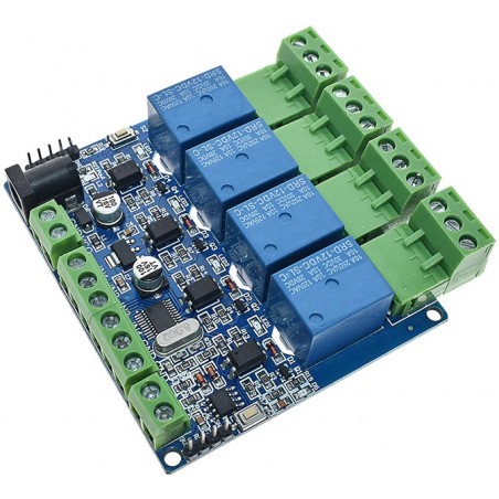

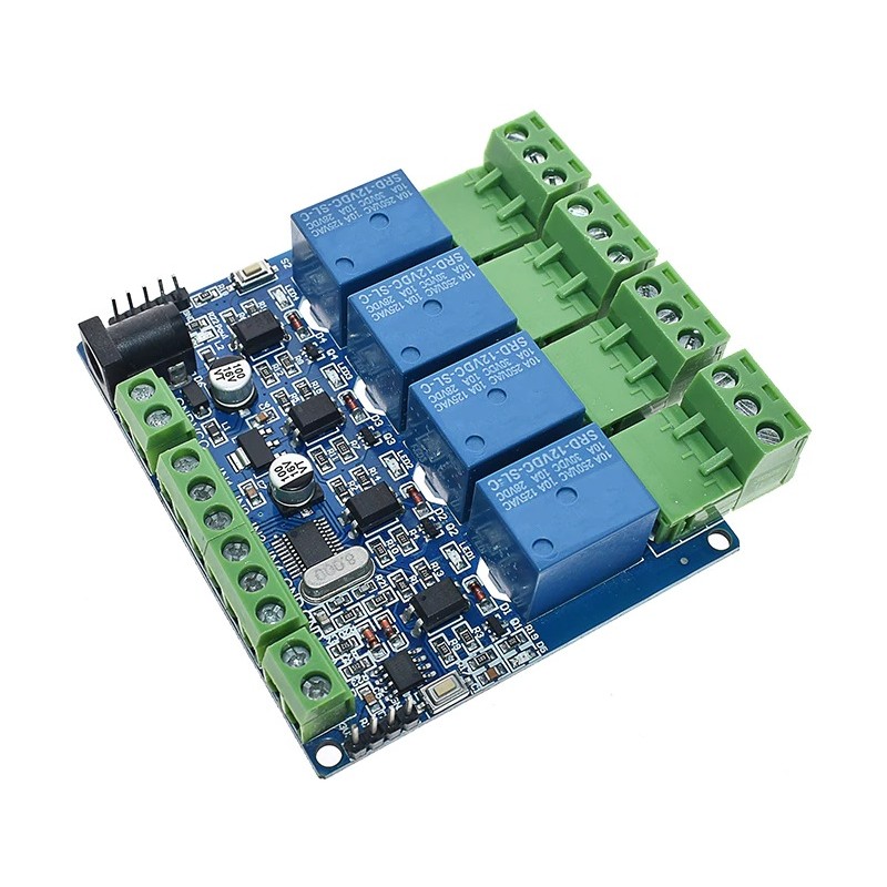
Com comunicação RS485 e compatível com o protcolo MODBUS RTU para melhor integração com autómatos industriais.
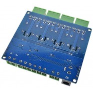
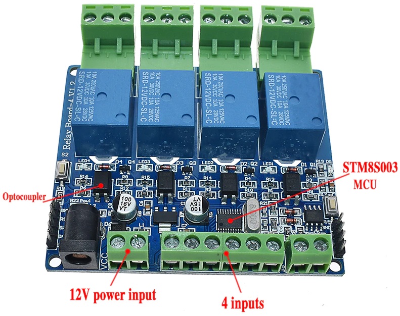
A alimentação é a 12Vdc e tem 4 saídas a relé que tanto podem ser controladas diretamente pelos 4 inputs correspondentes (isolados opticamente), bem como através do barramento de comunicação RS485 usando o protocolo MODBUS.
O endereço por defeito é o 1, que pode ser alterado ( ver instruções na descrição ).
DESCRIÇÃO EM PORTUGUÊS BREVEMENTE DISPONÍVEL
Se tiver alguma dúvida neste produto não hesite em contactar-nos.
*Atenção: as imagens são meramente ilustrativas.
Relay voltage: power supply 12V.
Relay communication: Multi-unit network 485 communication, based on MODBUS-RTU protocol, the default communication address is 1, users can modify the address by instructions
IN1-IN4 are connected to the switch. The switch status is read through 485, not through the input control relay output.
Note: IN1-IN4 cannot be connected to 230Vac (some buyers will make this mistake)
IN1-GND (default is high level, low level after the switch is turned on) The computer sends instructions to read the switch status.
IN2-GND (default is high level, low level after the switch is turned on) The computer sends instructions to read the switch status.
IN3-GND (default is high level, low level after the switch is turned on) the computer sends instructions to read the switch status.
IN4-GND (default is high level, low level after the switch is turned on) The computer sends instructions to read the switch status.
1. Set the address to
2. Read the address
3. Read the software version
4. Read the hardware version
MODBUS-RTU communication instruction:
Function code: 05 is the relay output [control relay on/off]
Function code: 06 is stored data [user-defined storage data, user-defined data, address number, set by the user. Generally useless]
/**********************************************************************/
Modbus RTU instruction
Baud rate: 9600 8 NONE 1
Send in hexadecimal
Hexadecimal reception
Steps:
1. The software sets the communication baud rate
2. Set the address (device address used for communication)
The instruction with address 1 set by default
/************************************************* ******************/
Set the address as: 01
Send: 00 06 40 00 00 01 5c 1b
Return: 01 06 00 00 00 01 48 0A
Set the address as: 02
Send: 00 06 40 00 00 02 1c 1a
Return: 02 06 00 00 00 02 08 38
Read address
00 03 40 00 00 01 90 1b
/************************************************* ******************/
Read software version
Send: 00 03 00 02 00 01 24 1b //【Sun】
Return: 01 03 02 10 00 B5 84 //No. 10
Send: 00 03 00 04 00 01 c4 1a //[month] Broadcast reading (only one device can be connected, practical for all addresses, convenient for testing)
Return: 01 03 02 4D 61 4C FC //4D[M] 61[A] MAR[March]
Send: 00 03 00 08 00 01 04 19 //【year】 Broadcast reading (only one device can be connected, practical for all addresses, convenient for testing)
Returns: 01 03 02 20 18 A1 8E //20 18 = 2018
Send: 00 03 00 10 00 01 84 1e //[Hour, Minute] //Broadcast reading (only one device can be connected, practical for all addresses, convenient for testing)
Return: 01 03 02 21 26 21 CE //21:26
Read hardware version (PCB version)
Send: 00 03 00 20 00 01 84 11 //Broadcast reading (only one device can be connected, practical for all addresses, convenient for testing)
Return: 01 03 02 00 6A 38 6B //6A = 106 =V1.06
Send: 01 03 00 20 00 01 85 c0
Return: 01 03 02 00 6A 38 6B //6A = 106 =V1.06
/************************************************* ******************/
[Address 1]
//--------------------------------------------
Relay 0 turns on: 01 05 00 00 FF 00 8C 3A
Relay 0 is off: 01 05 00 00 00 00 CD CA
//--------------------------------------------
Relay No. 1 turned on: 01 05 00 01 FF 00 DD FA
Relay No. 1 is closed: 01 05 00 01 00 00 9C 0A
//-------------------------------------------
Relay No. 2 turned on: 01 05 00 02 FF 00 2D FA
Relay No. 2 is off: 01 05 00 02 00 00 6C 0A
//-------------------------------------------
Relay No. 3 turned on: 01 05 00 03 FF 00 7C 3A
Relay No. 3 is closed: 01 05 00 03 00 00 3D CA
Single flip instruction:
No. 0 relay flip: 01 05 00 00 55 00 F2 9A
No. 1 relay flip: 01 05 00 01 55 00 A3 5A
No. 2 relay flip: 01 05 00 02 55 00 53 5A
No. 3 relay flip: 01 05 00 03 55 00 02 9A
Fully closed: 01 05 00 ff 00 00 fd fa
Fully open: 01 05 00 ff ff ff fc 4a
Full flip: 01 05 00 ff 5a 00 c7 5a
/************************************************* *********************/
Read relay status 0: 01 01 00 00 00 01 FD CA
Read the status of relay No. 1: 01 01 00 01 00 01 AC 0A
Read the status of relay No. 2: 01 01 00 02 00 01 5C 0A
Read the status of relay No. 3: 01 01 00 03 00 01 0D CA
Relay No.1 Read all channel status: 01 01 00 FF 00 00 3d c9
/************************************************* ********************/
Read all interface input status
01 02 00 00 00 00 78 0a
return:
01 02 01 01 60 48 //IN1 press
01 02 01 02 20 49 //IN2 press
01 02 01 04 A0 4B //IN3 press
01 02 01 08 A0 4E //IN4 press

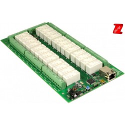
Produtos Associados

Com comunicação RS485 e compatível com o protcolo MODBUS RTU para melhor integração com autómatos industriais.
A alimentação é a 12Vdc e tem 4 saídas a relé que tanto podem ser controladas diretamente pelos 4 inputs correspondentes (isolados opticamente), bem como através do barramento de comunicação RS485 usando o protocolo MODBUS.
O endereço por defeito é o 1, que pode ser alterado ( ver instruções na descrição ).