- DISCONTINUED
-
MenuBack
-
Menu
-
Arduino & Raspberry & Micro:bit
-
-
-
-
-
Controller Boards
-
-
-
Batteries
-
Components & TOOLS
-
-
e-Textil
-
-
-
Interruptores & Botões
-
-
-
Sound and Audio
-
-
-
Comunication & Smart Home
-
-
LCD + Matrix + Keypad
-
-
Power Sources and Renewable Energy
-
-
-
RENEWABLE ENERGY
-
-
-
3D Printing & DRONES
-
-
Informática
-
-
Informática
-
-
-
Motors and Relays
-
-
Oficina & Equipamentos
-
-
Oficina & Equipamentos
- Cable ties
- Pliers and Wrenches
- Breadboards
- Drills and Milling Cutters
- Storage Boxes
- Electronics boxes
- Bench Equipment
- Tool Cases & Kits
- Heat shrink sleeve
- Multimeters
- Oscilloscope
- Screws and Spacers
- PCB Copper
- End-Sleeves
- IC Programmers
- Personal Protection
- Protoboards
- Soldering
- Spray and Conductive Paint
- DIN Rail Supports
- Others
-
-
-
ROBOTICS
-
-
Sensors
-
-
- Catalog
- New Products
- On Sale
- Tutorials
- Contact
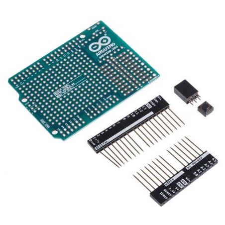
Arduino Proto Shield Rev3
- Arduino 1.0 pin out
- Large 0.1inch prototyping area
- Reset button
- 14pin SMD footprint (50mils pitch)
- 20pin through hole footprint (100mils pitch)
- SPI header
- Long and easy to solder ground/5V rails
Description
Board features as follows:
- 1.0 Arduino pinout
- 1 Reset button
- 1 ICSP connector
- 14 pins SMD footprint (50 mils pitch)
- 32 double row through Hole pads, standard Arduino breakout layout
- Proto aerea with multiple THT pads, 100 mils pitch
Power
The Proto Shield bring the power from the Arduino standard 5V and GND pins to the two power bus rows placed between the Through Hole package footprint, which can be used for powering the DIP sockets, or for power and ground rows.
Physical Characteristics
The maximum length and width of the Proto Shield PCB are 2.7 and 2.1 inches respectively. Three screw holes allow the shield to be attached to a surface or case. Note that the distance between digital pins 7 and 8 is 160 mil (0.16"), not an even multiple of the 100 mil spacing of the other pins.
SPI Connection
On the ICSP connector only 5V, GND and RST are wired to the respective pins on the header. MOSI and MISO are present only on the connector pads.
For more information about the SPI communication see the SPI library.
Schematic & Reference Design
EAGLE files: arduino-proto-Shield-reference-design.zip
Schematic:arduino-proto-Shield-reference-design.pdf
Related products