- DISCONTINUED


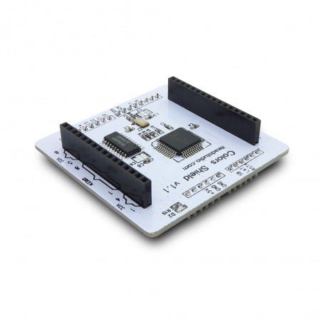
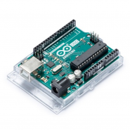
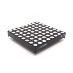
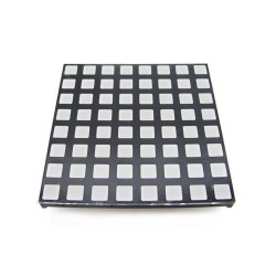
The Colors shield can directly plug on the Arduino board, and hook up with the RGB LED matrix, you can use the Arduino to drive the matrix like the Colorduino/Rainbowduino.
If you have any questions on this product please feel free to contact us.
*Disclaimer: The images are merely illustrative.
The Colors shield can directly plug on the Arduino board, and hook up with the RGB LED matrix, you can use the Arduino to drive the matrix like the Colorduino/Rainbowduino. The code of Colors shield is the same as Colorduino.
The Colors shield can be plug on the Arduino UNO/Duemilanove, so the controller is basis on ATMega 168P/328P, the same as Rainbowduino. This design is to make user easily modify or write the firmware of Colorduino by Arduino IDE. But in order to better drive the RGB matrix and reach their best performance, we use the professional LED driver chip, and this chip comprises shift registers, data latches, 8×3 channel constant current and 64 x 256 gray level PWM for per color! Each channel provide a maximum current of 60 mA.
Each RGB dot has 160K colors in theory, and it’s easy to use the 6bit correction register to calibrate the current error for each color LEDs – we don’t think that Rainbowduino use an adjustable resistors to calibrate the current error is a good idea, because just 1 lap the resistor change from 0R to1K , you cannot get the exact value you need, but now, you have a 6bit software value to correct it.
Videos (arduino Uno + color shield + matrix 8x8 RGB LED)
Direct shop link: Arduino Uno and matrix RGB LED
|
Pad Name |
Type |
Description |
|
SDA |
I |
Serial input for grayscale data |
|
SCK |
I |
Synchronous clock input for serial data transfer. The input data of SDA is transferred at rising edges of SCK. |
|
SB |
I |
If SB is H, shift-in data would be stored in the 8-bit BANK 1. If SB is L, shift-in data would be stored in the 6-bit BANK 0. |
|
LAT |
I |
When LAT converts from H to L, grayscale data in both shift register banks are latched. |
|
RSTn |
I |
The shield is initialized when RSTn low. There is an internal pull-up in this pin. This pin couldn’t be floating. Before using the shield, it must be reset first. |
|
C0 |
I |
Channel 0 enable input, High level active |
|
C1 |
I |
Channel 1 enable input, High level active |
|
C2 |
I |
Channel 2 enable input, High level active |
|
C3 |
I |
Channel 3 enable input, High level active |
|
C4 |
I |
Channel 4 enable input, High level active |
|
C5 |
I |
Channel 5 enable input, High level active |
|
C6 |
I |
Channel 6 enable input, High level active |
|
C7 |
I |
Channel 7 enable input, High level active |
|
+5V |
Power |
Power supply for Color shield, input range is from +3.3V to 5V. |
|
GND |
GND |
|
Specification
| Version | 1.1 |
|---|---|
| Compatible Mainboard | Arduino Deumlanove/UNO Arduino MEGA Iteaduino Iteaduino BT Iteaduino ADK Iteaduino MEGA 2560 Iteadmaple Simple Cortex ChipKit UNO32 ChipKit MAX32 FEZ Panda II Freeduino Leaf maple Seeeduino Seeduino MEGA |
| Shield Functions | Display |
| Board Size | 60mm x 60mm |
| Operation Level | Digital 3.3V Digital 5V |
| Stackable | No |
| Model | IM120417002 |
| Accessories | N/A |
| Weight | 35.00g |
Related products


The Colors shield can directly plug on the Arduino board, and hook up with the RGB LED matrix, you can use the Arduino to drive the matrix like the Colorduino/Rainbowduino.
